

Threads of the highest surface quality can be produced with minimum machining times using the Wagner tangential rolling system.
Optimum productivity is achieved using precise thread rolls with maximum tool life. The diameter, pitch and shape of the rolls are adapted to the thread to be rolled. Wagner tangential rolling tools are available in various sizes and are suitable for machining workpieces from Ø 1.6–52 mm.
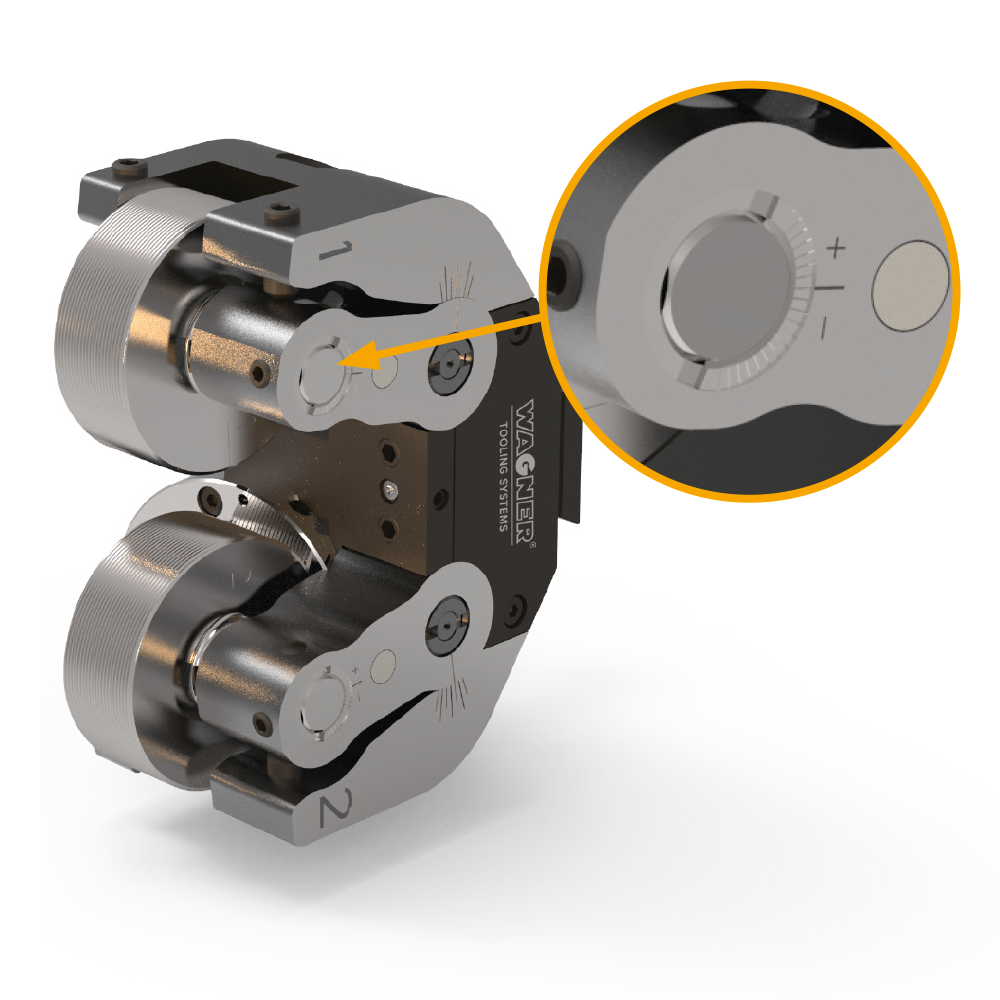
Premium rolling results in fine-pitch threads can be achieved by using our tool variant “F”. For threads with very small pitches, it is important to keep the axial play of the thread rolls as low as possible. By means of the patented Wagner axial play fine adjustment, the axial roll play can be minimized in 0.02 mm steps. The fine adjustment is available as an option.
Profile rolls for special applications such as rolls for lubrication grooves, knurling or smoothing are also available.
AREAS OF APPLICATION
- cylindrical and conical threads, right- and left-hand threads as well as regular and fine threads
- threads behind a collar
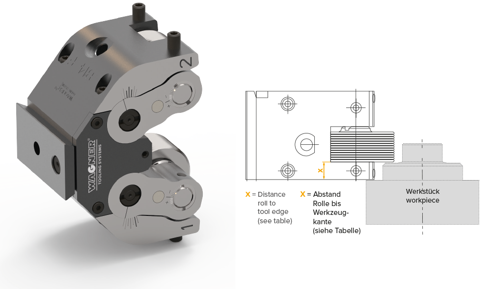
- threads close to a collar
- very short threads
- threads where the end of the workpiece is not free
- threads with very short run-outs
ADVANTAGES
- very short processing time
- large working range
- long tool life due to large rolls and high rigidity of the tool body
- particularly low-maintenance
- the rolled threads are suitable for high loads due to their uninterrupted fibre course.
- durable, wear-resistant and corrosion-resistant threads
- high flexibility due to numerous adapter variants for use on different machines, e.g. single and multispindle lathes as well as special machines
TYPE STANDARD
Maximum stability with large working range.
| Type | Standard thread Ø | - | Fine thread Ø | - | Thread length max. (minus 2 x thread pitch) |
Distance roll to tool edge (X) | Max. Feed force N |
Weight in kg | - |
| " | mm | zoll | mm | zoll | " | " | " | Tool with rolls | Adapter |
| B8-W | 1.6–12 | 0.063–0.473 | 1.6–13 | 0.063–0.512 | 14 | 7 | 1600 | 0.9 | ca. 1.5 |
| B10-W | 2–16 | 0.08–0.63 | 2–16 | 0.08–0.63 | 19 | 10.1 | 2500 | 1.9 | ca. 1.7 |
| B11 | 2–16 | 0.08–0.63 | 2–16 | 0.08–0.63 | 19 | 10.1 | 2500 | 1.9 | ca. 1.7 |
| B13 | 3–22 | 0.12–0.866 | 3–30 | 0.12–1.181 | 22.6 | 13.4 | 4900 | 3.8 | ca. 2.0 |
| B14 | 4–22 | 0.157–0.866 | 4–35 | 0.157–1.375 | 25,5 | 13.5 | 5000 | 3.5 | ca. 2.0 |
| B16 | 6–22 | 0.236–0.866 | 6–45 | 0.236–1.77 | 25,5 | 13.5 | 5700 | 3.7 | ca. 2.0 |
| B19 | 8–27 | 0.315–1.06 | 8–52 | 0.315–2.05 | 34,5 | 16.5 | 9800 | 7.5 | ca. 3.0 |
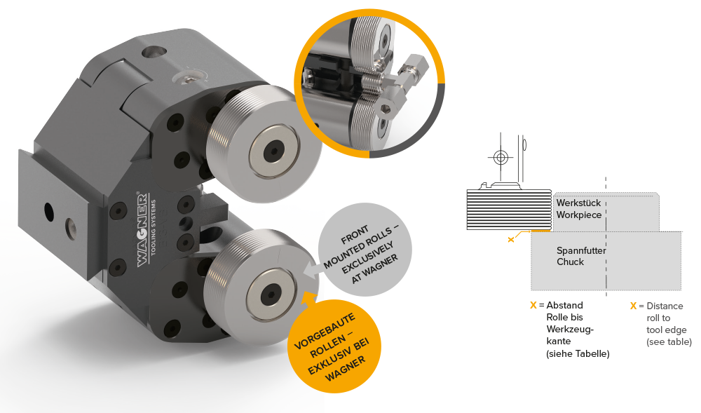
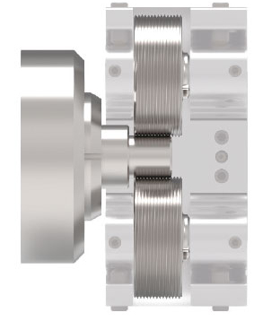
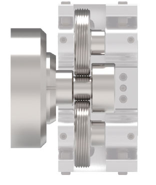
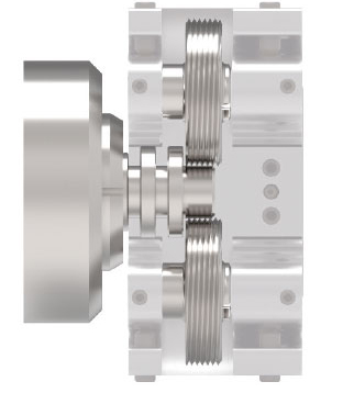
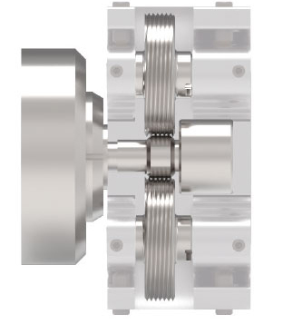
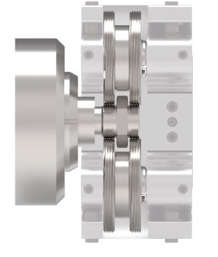
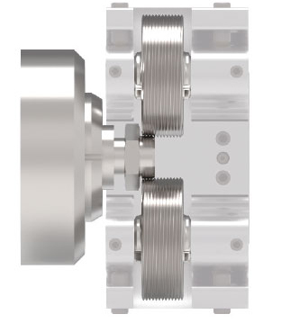
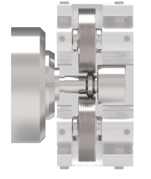
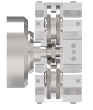
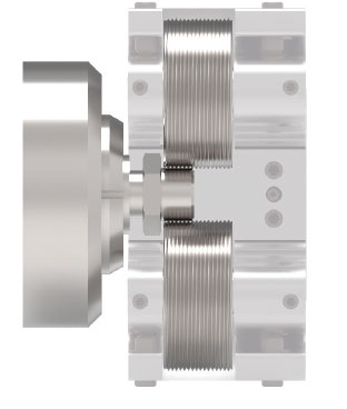
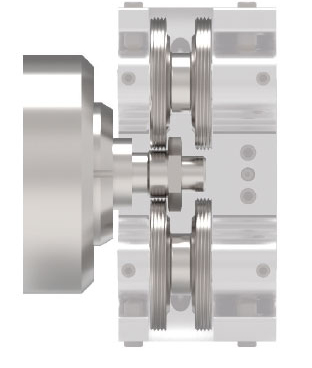
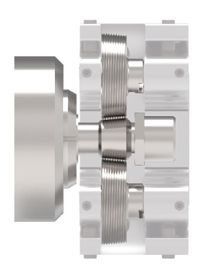
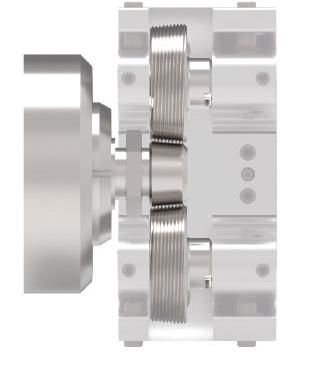
TANGENTIAL SYSTEM WITH FRONT MOUNTED ROLLS
Tangential rolling tools with front mounted rolls are available exclusively from Wagner. Within the shortest machining times, it is possible to roll threads directly up to the collar or the chuck.
| Typ | Regelgewinde Ø | - | Feingewinde Ø | - | Gewindelänge max. (minus 2 x Gewindesteigung) mm |
Max. Vorschubkraft N |
Gewicht in kg | - |
| " | mm | zoll | mm | zoll | " | " | Werkzeug mit Rollen |
Adapter |
| B13-VB | 3–10 | 0.12–0.394 | 3–24 | 0.12–0.945 | 17 | 4000 | 4,5 | ca. 2.0 |
| B16-VB | 8–16 | 0.315–0.63 | 8–42 | 0.315–1.654 | 20 | 4000 | 5,4 | ca. 2.0 |
VORTEILE
- Arbeitsbereich M3–M42 / UN 5–40 bis UN 15/8″
- Problemlöser für anspruchsvolle Werkstückgeometrien und spezielle Werkstückaufspannungen
- Für höchste Gewindequalität
- Prozesssicherheit durch Hochleistungs-Gewinderollen
- Einfache Bedienung und schneller Rollenwechsel
- Kürzeste Bearbeitungszeiten
- Ideal z. B. für Edelstahlverschraubungen
TYPE VARIANT F
Quick and easy adjustment of the AXIAL ROLL PLAY for best thread quality and long tool life for Type “F”. Especially recommended for fine threads.
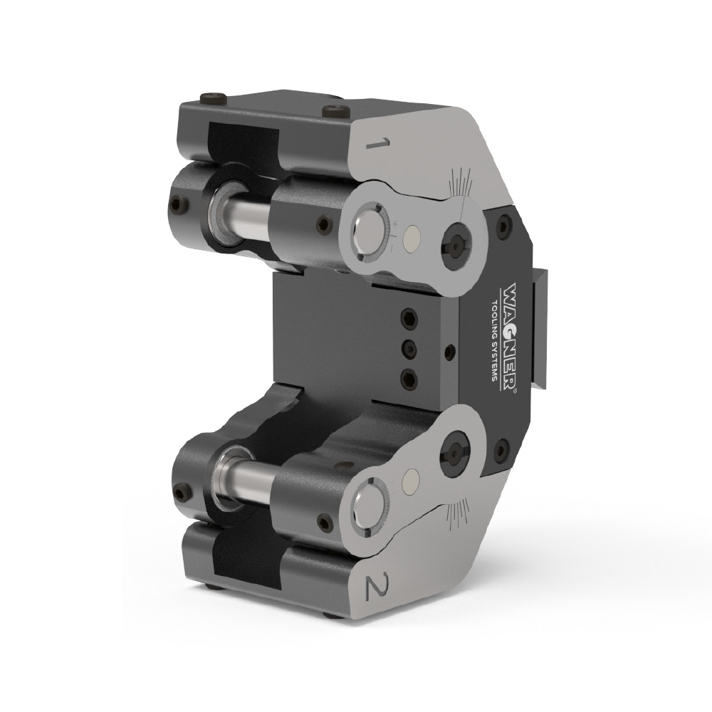
REINFORCED DESIGN
ROLL FORM AND SELECTION CRITERIA
Depending on the application, different types of thread rolls can be used. The roll form DR is not possible for all threads and must be clarified for each individual case.
C1-Rolls
Standard roll with full profile width with one-sided, non recessed driving slot
C2-Rolls
Rolls with profile width matched to the thread length for rolling behind a collar
C3-Rolls
Rolls with profile width matched to the thread length and clamping length for rolling in front of a collar
C4-Rolls
Rolls with profile width matched to the thread length and clamping length for rolling behind a collar
C5-Rolls
Two threads of the same dimension can be rolled simultaneously
CR1-Rolls
For the production of short threads. Tool life can be doubled by turning the rolls
CR4-Rolls
For the production of short threads behind the collar. Tool life can be doubled by turning the rolls
CR5-Rolls
For rolling a short thread behind a narrow collar. Tool life can be doubled by turning the rolls
DR1-Rolls
It should be possible to turn the rolls (double the tool life). The driving slots are recessed, as the profile width of the CR1 rolls is not sufficient.
DR5-Rolls
For rolling a short thread behind a narrow collar. Double the tool life by turning the rolls. The driving slots are countersunk, as the profile width of the CR5 roll is not sufficient.
K2-Rolls
For rolling a tapered thread behind the collar (tapping side)
Q2-Rolls
For rolling tapered threads at the open end of the workpiece
DIMENSIONS OF THE THREAD ROLLS
The dimensions for the individual shapes of the thread rolls can be taken from the following table:
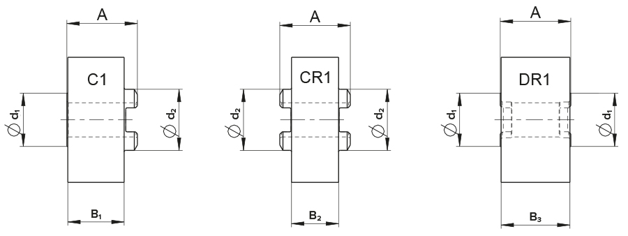
| B1 | B2 | B3 | d1 | d2 | |
| B8 | 12.2 mm | 10.8 mm | 14.2 mm | 12.9 mm | 14.4 mm |
| B10–B11 | 15.8 mm | 13.2 mm | 19.3 mm | 14.9 mm | 17.1 mm |
| B13–B16 | 22.6 mm | 19.7 mm | 25.75 mm | 20.1 mm | 21.8 mm |
| B19 | 31.2 mm | 28.5 mm | 34.5 mm | 23.3 mm | 25.2 mm |
THREAD RUN-OUT, THREAD UNDERCUT
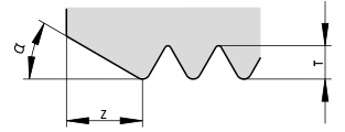
The thread rolls are chamfered at an angle α. For workpieces without undercut, the angle α = 30° should be used. Angle α = 45° or 60° is used when the last full thread of the workpiece must be very close to a collar and only for workpieces with undercut.
α = angle of the chamfer on the thread roll
Z = width of the chamfer
T = depth of the thread profile
The thread rolls and the collar of the workpiece must not touch each other, i.e. a safety distance must be provided. The required distances are shown in the illustrations.
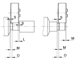
Clearance dimensions tangential rolls
S = safety clearance (min. 0.3 mm)
L = required thread run-out ( = Z + S)
M = required overhang of the thread roll in the undercut
O = required width of the thread undercut (= M + S)
| α = 30° | α = 45° | α = 60° | |
| Z | 1,84 × T | 1,06 × T | 0,62 × T |
| L | 2,65 × T | 1,88 × T | 1,42 × T |
| M | 2,24 × T | 1,46 × T | 1,02 × T |
| O | 3,05 × T | 2,28 × T | 1,84 × T |
| Thread type | Standard | Thread depth = thread pitch × factor |
| Metric ISO | DIN | T = P × 0.62 |
| UN | ANSI | T = P × 0.62 |
| Whitworth Whitworth pipe |
BS | T = P × 0.65 |
| Trapezoidal | DIN | T = P × 0.5 + 0.25 |