

THE PROCESS
In thread rolling the thread form is produced by cold forming the material. Very high pressure causes permanent plastic deformation of the material. The thread rolls displace the material from the thread core and allow flow in the direction of the thread crests. The grain structure is not interrupted but only displaced. The result is a thread with high strength, profile and dimensional accuracy.
The pre-turned diameter required for thread rolling corresponds to the pitch diameter of the thread. The tolerance is selected so that the desired major diameter of the thread is achieved, but the thread crests are not fully formed. A change in the pre-turned diameter can have an effect on the major diameter of up to 3–5 times. Therefore, a pre-turned diameter that is 0.02 mm larger can result in a major diameter that is up to 0.1 mm larger. Fully formed thread crests have a negative effect on the roll tool life and can lead to roll breakage.
TYPE HELIX
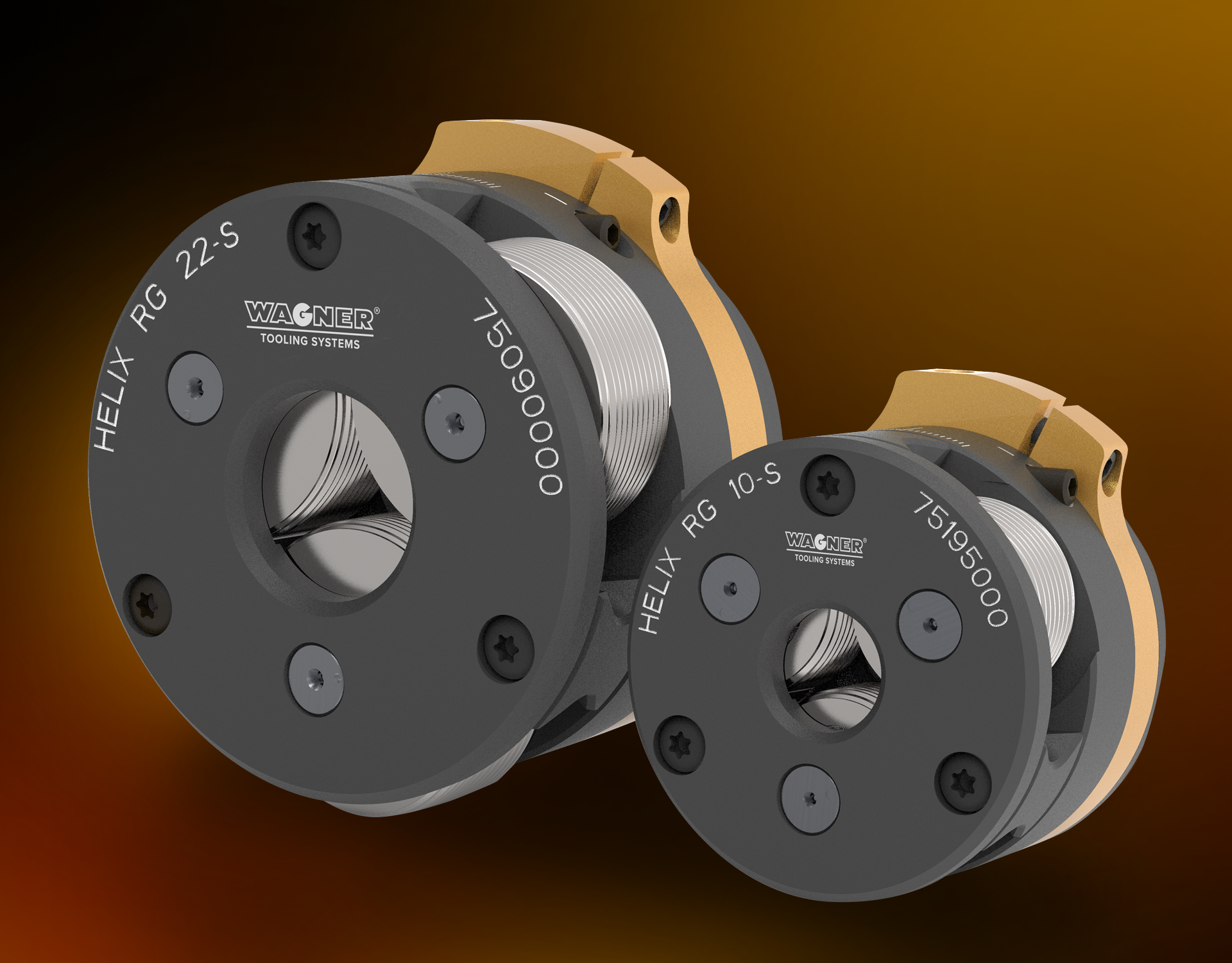
HELIX axial thread rolling systems are available in three different sizes and various versions, which can be used to produce threads from M6 to M22 or 1/4" to 7/8".
TYPE RS/RR WITH ROLL HOLDER
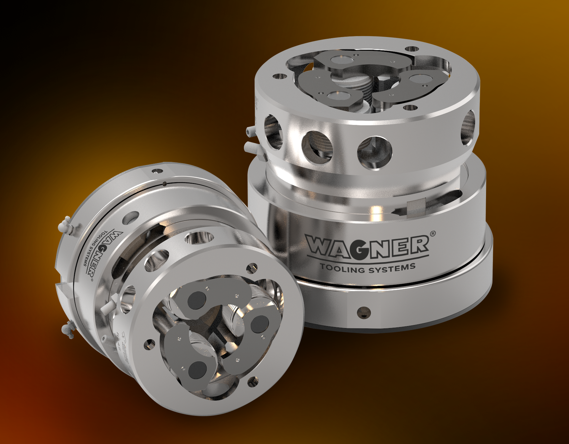
The large working ranges (M2.5–M75) of the individual roller system types are made possible by the quick and easy replacement of the roller holders. These differ in terms of their working range and holder angle.
ALLGEMEINE RAHMENBEDINGUNGEN ZUM AXIALEN GEWINDEROLLEN
PREPARATION OF THE WORKPIECE
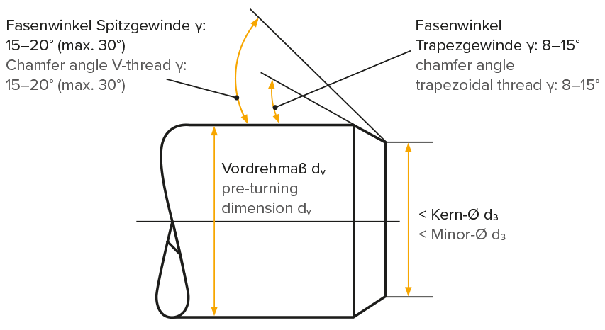
The workpiece must be prepared to the pre-turned diameter dV, additionally a chamfer and, if necessary, a thread undercut must be turned.
The pre-turned diameter dV corresponds to the pitch diameter d2 of the thread. The permissible tolerance depends on the desired thread filling degree and the thread pitch. The finer the thread pitch, the smaller the tolerance must be kept during pre-turning.
dv ≈ d2
NOTE:
It should be noted that a change in the preturning diameter has an effect on the major diameter by a factor of three to five
NOTE:
Chamfer the workpiece for V-threads with γ = 15–20° (max. 30°) and for trapezoidal and round threads with γ = 8–15°.
The diameter d1 should be at least 0.2 mm smaller than the minor diameter d3 of the thread.
d1 ≤ d3 − 0.2 mm
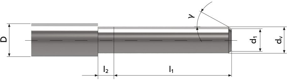
Pre-machined workpiece without undercut
D = shoulder diameter
dv = pre-turned diameter
d1 = diameter at the beginning of the chamfer
l1 = thread length
l2 = length of thread run-out
γ = chamfer angle
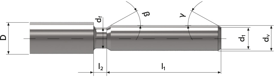
Pre-machined workpiece with undercut
D = shoulder diameter
dv = pre-turned diameter
d1 = diameter at the beginning of the chamfer
l1 = thread length
l2 = width of the thread undercut
γ = chamfer angle
β = run-out chamfer
df = diameter in undercut
THE THREAD RUN-OUT
The smallest possible thread run-out or thread undercut l2 depends on:
> the thread pitch
> the lead of the thread roll
The roll lead indicates the forming stages of the roll set, e.g.
A3:
3 deformation stages, i.e. the first tooth of roll 3 forms to full thread depth.
a ≈ 1.5 × P
A4 (Standard):
4 deformation stages, i.e. the second tooth of roll 1 forms to full thread depth.
a ≈ 2 × P
A7:
7 deformation stages, i.e. the third tooth of roll 1 forms to full thread depth.
a ≈ 3 × P
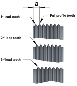
Example A4-roll lead
DETERMINATION OF THE THREAD RUN-OUT
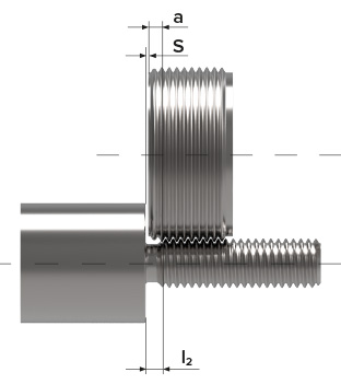
l2 = a + s
l2 = smallest possible thread run-out or undercut width
a = distance to the first full profile tooth
s = safety distance of the roll to the workpiece collar
Example thread M12 × 1.5:
a = 2.8 mm
s = selected 0.5 mm
l2 = 2.8 + 0.5 = 3.3 mm
SETTING THE THREAD LENGTH (FORMING LENGTH) ON THE MACHINE
Conventional machine
- Make sure that the rolling system is open, if necessary open it manually.
- Move the rolling system to the desired end position. This position can be determined by the internal stop of the rolling system or by a stop on the machine and is selected so that the desired thread or forming length is achieved.
- Move back to the start position of the rolling process.
- Close the rolling system manually by turning the closing lever until the coupler engages.
CNC machine
- Measure the rolling system in open condition.
- Calculate the traverse path.
- Program the traverse path with the machine control.
- Program the feed stop with a short dwell time when the end postion has been reached so that the rolling system opens automatically.
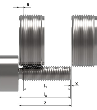
CALCULATE THE TRAVERSE PATH
z = lU + x = l1 + a + x
z = traverse path
l1 = usable thread length
lU = forming length incl. thread run-out
a = thread run-out
x = safety distance to the workpiece
(when determining x, it must be taken into account that the rolling tool is shorter in closed condition). (opening stroke s = depends on the tool)
CALCULATE THE DWELL TIME

ts = dwell time
s = opening stroke of the rolling tool
n = spindle speed [1/min]
f = feed [mm]