

The Wagner thread cutting system is an axially operating precision tool that produces threads of the highest quality in a short time. It is available in stationary and rotary design.
The stationary thread-cutting system is connected to the tool carrier, e.g. turret, via a tool holder. The tool moves axially onto the workpiece at a precise feed rate, cutting the thread in a single operation. When the feed is stopped, the opening mechanism of the tool is triggered. The chasers release the workpiece and the return movement in rapid traverse can take place. The tool is closed by axial movement of the closing lever or by a closing device.
AREAS OF APPLICATION
- regular, fine, cylindrical or conical threads, right-hand or left-hand threads, pipe, trapezoidal, round and special threads
- threads according to British and American standards
- parallel profiles by infeed profile cutting possible
- the most difficult machining tasks and large diameters can be performed effortlessly with the WDK-WKK cutting system types.
WAGNER CHASERS/THREAD CUTTING PLATES
- standard: HSS or HSSE
- nitrated
- coated: TiN, TiCN, TiAlN, CrN
- carbide
- customized according to customer requirements
ADVANTAGES
- by exchanging the chasers, different thread types can bemachined with only one cutting system
- high efficiency due to regrindable chasers
- short set-up times due to preset chasers
- time-saving operation due to single cut
- high-precision thread chasers adapted in pitch and shape to the thread to be cut
- high flexibility on almost all machines due to commercially available tool holders
TYPES OF WAGNER THREAD CUTTING SYSTEMS
TYPE COMPACT
The compact and flexible thread cutting systems from Wagner are fast, small and light. In four sizes, they cover a working range from Diameter 1.6 to 60 mm. They are available as stationary and rotating versions. Please note that this type should be used in the upper third of the working range only for materials with good machinability and tensile strengths below 700 N/mm2.
TYPE STANDARD
The standard thread cutting systems are available in one stationary version for lathes and six rotating versions for use on thread cutting machines, transfer and special machines.
TYPE HEAVY
The HEAVY rotary threading systems are used for heavy-duty cutting work on threading machines and other special machines. Their field of application ranges from large V-threads, pipe threads (up to 6 inches) to round and trapezoidal threads. The largest thread cutting system is equipped with five chasers.
DESIGN OF THE THREAD CUTTING SYSTEMS
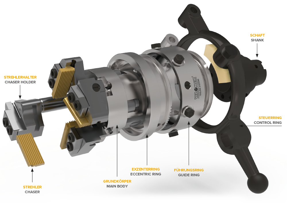
THE CHASERS
The chasers are the actual cutting tools. They carry the profile of the thread to be cut.
THE CHSER HOLDER
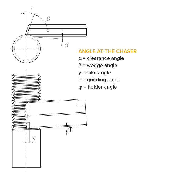
The chasers are held and clamped in the chaser holders. The so-called holder angle determines the inclined position of the chasers and must correspond approximately to the pitch angle of the thread to be cut. By changing the chaser holder types, the flexible working range of the cutting systems is achieved.
THE MAIN BODY
The chaser holders are mounted and axially held in the main body. The main body is connected directly or via a flange or shank to the tool spindle or the tool carrier of the machine.
THE ECCENTRIC RING AND GUIDE RING
The eccentric ring and guide ring form an assembly. They are mounted on the main body in a way so that they can be moved axially. This enables the opening function of the cutting system. By turning the eccentric ring, the chaser holder determines the radial position of the chasers and thus the machining diameter.
THE SHANK
The shank forms the interface to the machine and can accordingly be delivered for all common systems.
THE CHASER HOLDERS
The chaser holders are used to hold the chasers or cutting knives. They are graded according to different minor diameter ranges and have different holder angles, which are adapted to the pitch angle of the threads to be cut. The thread and holder tables simplify the selection of the correct chaser holder.
Haltertabellen
Chaser holders differ in:
1. holder type
2. working range
3. holder angle (approx. pitch angle of the thread)
4. set number
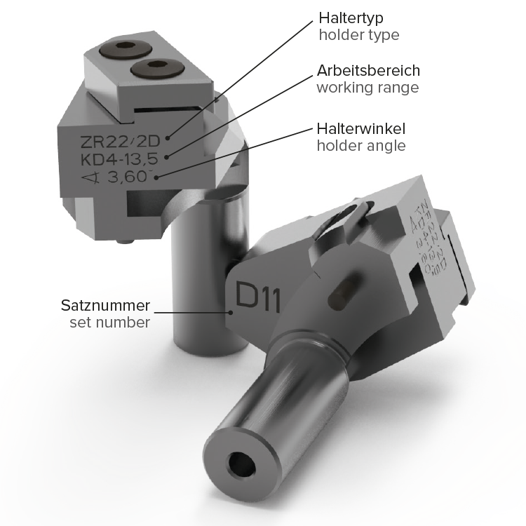
| ZR22 / 2D | Type 2D for ZA and ZR22 cutting tools |
| KD4-13,5 |
Working range from minor diameter 4 to 13.5 mm
|
| Winkel 3,60° | Holder angle must correspond approximately to the pitch angle of the thread |
| D11 | All four holders of the set must have the identical number |
THE CHASERS
The chasers have a parallel thread profile, i.e. with the same thread pitch, threads of different diameters can be cut with one chaser set (e.g. M6, M8 × 1, M10 × 1 ...). The appropriate chaser holders must be used according to the diameter and the pitch angle.
The size, the throat and thread profile of the chasers are adapted to the machining task, which means that they differ in the
1. thread profile (e.g. metric, UN, Whitworth ...)
2. throat (short, medium, long)
3. chaser quality (HSS, HSSE, nitrated, coated ...)
4. dimensions (chaser size S00–S15)
CHASER THROATS
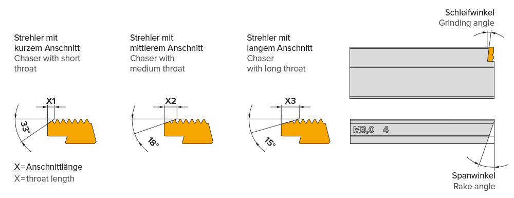
Short throat:
- for workpieces with threads against a collar or short thread undercuts
- thread run-out approx. 2 × thread pitch. For workpieces without or with small oversize and easily machinable materials
Medium throat:
- for blank or pre-turned workpieces with or without slight oversize.
- thread run-out approx. 3 × thread pitch
Long throat:
- for workpieces made of rolled material or with oversize.
- thread run-out approx. 4 × thread pitch
Custom-made throat:
- throats individually adapted to the application are possible
The length and angle of the throat influence the thread surface and tool life. The longer and flatter the throat, the longer the tool life and the better the surface.
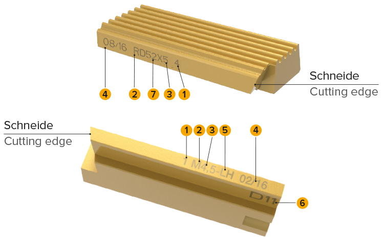
THE CHASER DESIGNATION
1 chaser number (1–4 = 4 pieces, 1–5 = 5 pieces)
2 profile shape (M = metric, RD = round thread, UN...)
3 thread pitch
4 serial number
optional:
5 LH for left-hand thread
6 set number (only for non-interchangeable chasers)
7 thread diameter
POWER REQUIREMENTS
The drive power required for thread cutting depends on the cutting speed, the material to be machined and the profile shape of the thread.
The following formula can be used to calculate the power requirement (Specifications without guarantee):
N ~ P2 ∙ Rm ∙ vc ∙ 0,00003 ∙ C [kW]
| P | thread pitch [mm] |
| Rm | tensile strength of the material [N/mm2] |
| vc | cutting speed [m/min] |
| C | factor 1 for V-threads, factor 2 for round and trapezoidal threads |
NOTE:
Factor 1.5 for cutting edge blunting is included in this formula. When cutting tapered threads to chaser width, a minimum factor of 2 must be taken into account.
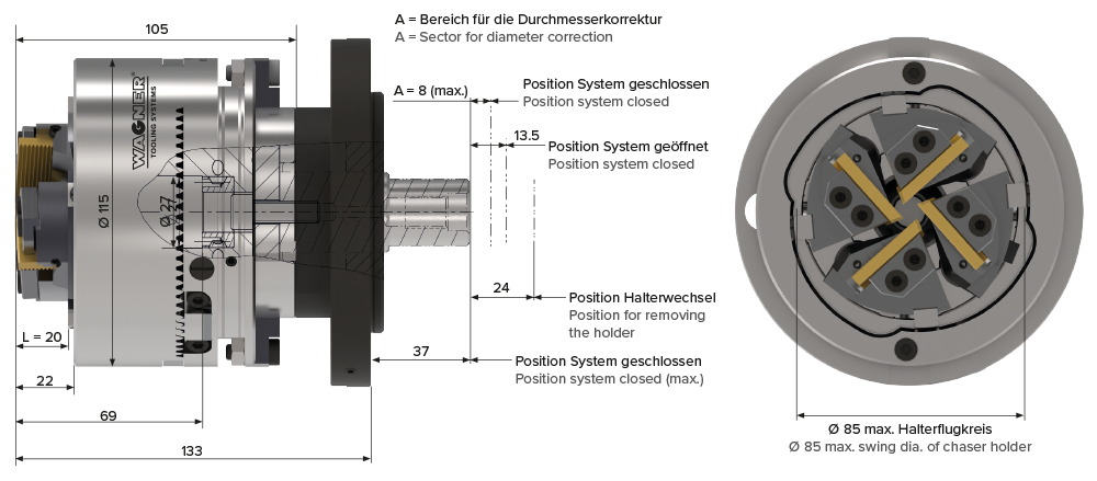
INTERNALLY CONTROLLED CUTTING SYSTEMS
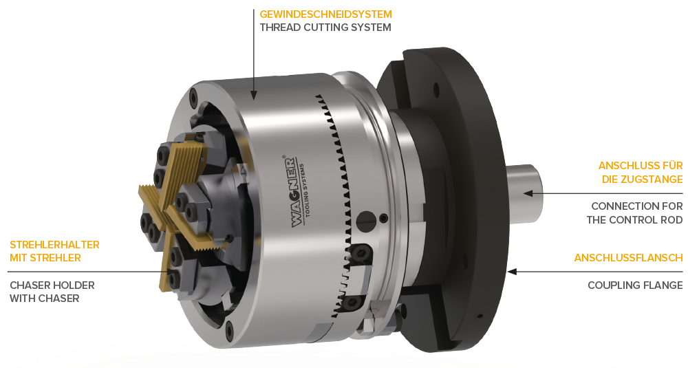
Internally controlled thread cutting systems are designed for use on machine tools with a control rod (cross feed). No external control linkage is required, the necessary control paths are executed via the internal control rod. The machine-specific coupling flange and the connecting piece for the control rod are supplied with the thread cutting system.
Apart from the cutting system ZR-26I, which is only offered as an internally controlled version, all cutting systems of the types ZR (compact) and Z (standard) are also available as internally controlled versions in addition to the standard version. The working ranges can be taken from the tables for the compact and standard systems, but the maximum achievable thread lengths are limited by the control rod.
| Type | Regular threads, nominal Ø | - | Fine threads, nominal Ø | - | Pipe threads, nominal Ø |
Size | - | Weight kg |
Thread length max. mm |
| " | mm | inch | mm | inch | inch | Tool Ø mm |
Tool length mm |
" | " |
| ZR26-I | 6–16 | 0.236–0.63 | 6–26 | 0.23–1.02 | 1/8–3/4 | 115 | 143 | 9 | 65 |
SPECIAL TYPES FOR CONICAL THREADS
Longer conical threads can be cut with the K and GK models, whereas with the standard systems, the thread length of tapered threads is limited by the chaser length. A conical eccentric ring and the conical sliding pieces on the chaser holders ensure that a continuous opening process takes place during cutting. Through this process, a high accuracy of the taper angle is achieved and good surfaces are obtained without lift-off marks from the chasers.
Continuous opening process:
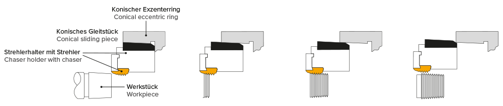
Example of a gas cylinder valve: The workpiece is pre-turned conically
1. special form K
The continuous opening process is triggered via the control ring by indirect control in a fixed lever ratio. In particular, conical pipe threads with a taper ratio of 1/16 on pipes, pipe nipples and fittings are cut with this.
2. special form GK
The control is direct, i.e. without transmission. Taper angles K 1:16, K 1:10, K 1:8, K 3:25 etc. can be achieved with exchangeable eccentric rings and sliding pieces. The areas of application are in the cutting of conical pipe threads on fittings and conical threads on gas cylinder valves.
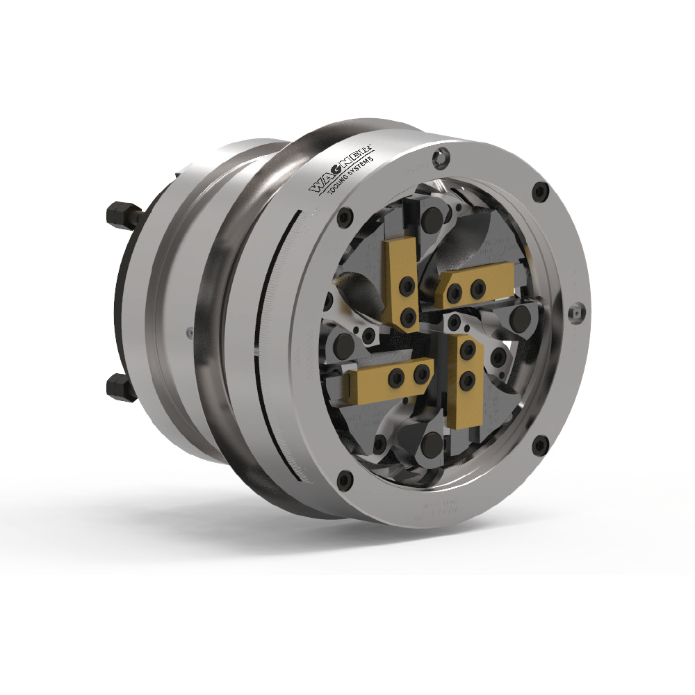
3. special form S
The special form S is a variant of the thread cutting system Heavy Duty. It is controlled directly via the ball-bearing control ring. This enables high cutting speeds of up to 40 m/min even with large thread diameters. The main area of application is the cutting of conical pipe threads from R 1/4 to R 6 or 1/4-18 NPT to 6-8 NPT.
| Type | Working Range | - | Conical Threads Length max. |
Size | - | Weight kg |
| " | Pipe Threads K1 / 16 | Gas Cylinder Threads | " | Ø mm | Length mm | " |
| Z16GK-2 | R1/8–3/4″ 1/8–3/4NPT |
1/8–3/4 NGT W 10.43–28,8 × 1/14 K3:25, K3:26, K1:8, K1:10 |
26 | 115 | 114 | 8 |
| Z27GK-2 | R1/8–1″ 1/4–1NPT |
1/4–1 NGT W 19.8–35.73 × 1/14 K3:25, K3:26, K1:8, K1:10 |
32 | 155 | 168 | 15 |
| Z27-K | R1/8–1″ 1/4–1NPT |
– | 34 | 155 | 155 | 15 |
| Z39-K | R1/8–2″ 1/4–2NPT |
– | 40 | 175 | 167 | 23 |
| WEK-S8 | R1/4–3″ 1/4–3NPT |
– | 44 | 310 | 260 | 84 |
| WHK-S3 | R1/2–4″ 1/2–4NPT |
– | 63 | 370 | 300 | 112 |
| WHK-S4 | R1–6″ 1–6NPT |
– | 57 | 410 | 320 | 140 |
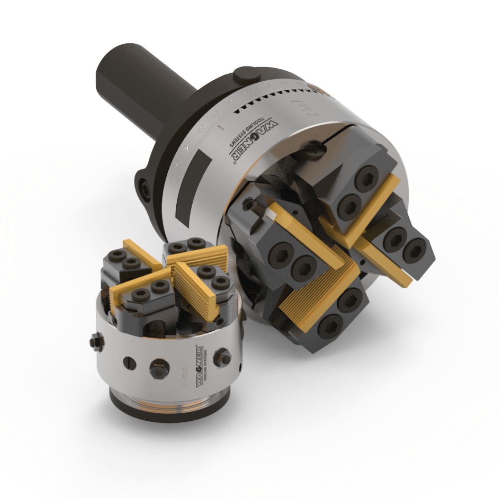
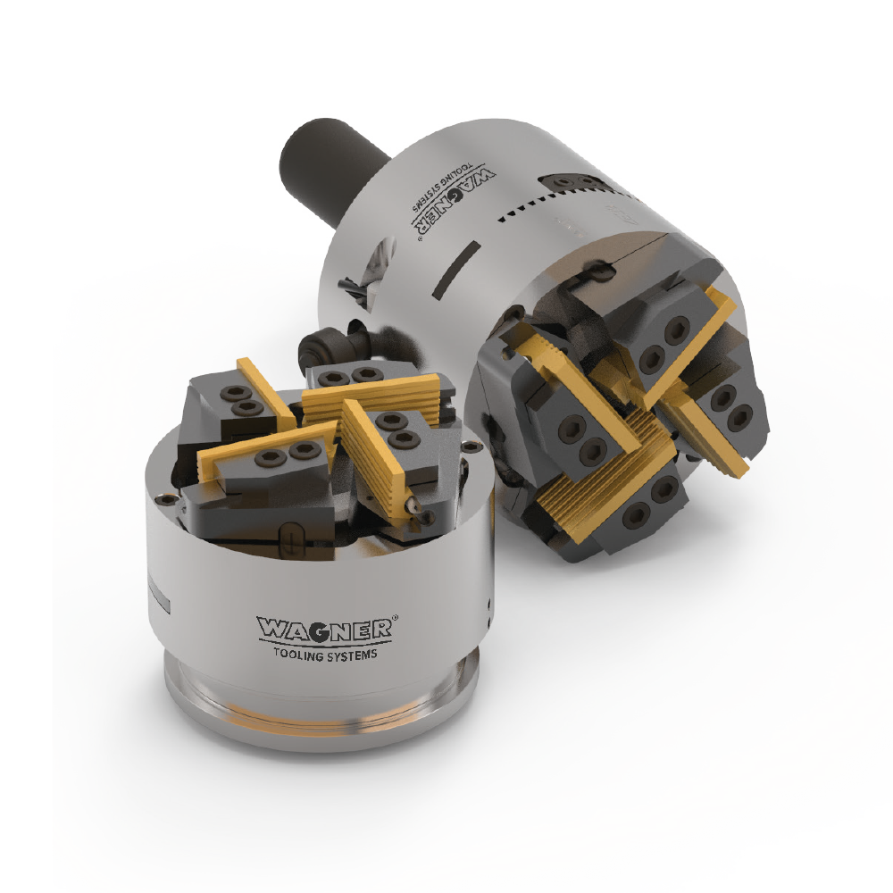
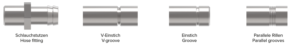
SPECIAL TYPES FOR GROOVING OPERATIONS
In addition to thread cutting, the Wagner cutting systems also offer the possibility of grooving. For this application, the eccentric ring and sliding pieces are equipped with a flat chamfer, which allows the chaser holders to be swivelled in with the grooving knives in a controlled manner. The cutting system is controlled by a pneumatic or hydraulic cylinder mounted on the machine, and the closing force is transmitted to the cutting system via a ball bearing. This allows you to cut parallel profiles, recesses, chamfers, or combinations of these, using infeed profile cutting. We adapt the required grooving knives or inserts to the shape of your groove.
ADVANTAGE
Centric machining on four sides prevents the work piece from bending due to the cutting force.
| Typ | Working Range mm / Inch (Minor Ø of the groove) |
- | Profiling depth max. |
- | Size | - | Weight kg |
| " | mm | inch | mm | inch | Ø mm | Length mm | " |
| ZR16-E | 0–16.8 | 0.04–0.66 | 1.75 | 0.069 | 66 / 80 | 75 | 2 |
| ZR22-E | 1.7–18 | 0.067–0.71 | 2.3 | 0.09 | 82 / 95 | 90 | 3 |
| ZR27-E | 1–35.1 | 0.04–1.38 | 3 | 0.12 | 155 | 105 | 6.5 |
| REK-1 | 0.5–16 | 0.02–0.63 | 4 | 0.157 | 95 | 64 | 2.2 |