CHIPLESS EXTERNAL THREAD PRODUCTION - THREAD ROLLING
THREAD ROLLING – GENERAL CONDITIONS
THE PROCEDURE
In thread rolling the thread form is produced by cold forming the material. Very high pressure causes permanent plastic deformation of the material. The thread rolls displace the material from the thread core and allow flow in the direction of the thread crests. The grain structure is not interrupted but only displaced. The result is a thread with high strength, profile and dimensional accuracy.
The pre-turned diameter required for thread rolling corresponds to the pitch diameter of the thread. The tolerance is selected so that the desired major diameter of the thread is achieved, but the thread crests are not fully formed. A change in the pre-turned diameter can have an effect on the major diameter of up to 3–5 times. Therefore, a pre-turned diameter that is 0.02 mm larger can result in a major diameter that is up to 0.1 mm larger. Fully formed thread crests have a negative effect on the roll tool life and can lead to roll breakage (see picture below left).
PRECONDITIONS
- exact pre-turned dimension
- elongation percentage of the material > 5 %.
- material strength up to approx. 1700 N/mm2
PREPARATION OF THE WORKPIECE
The workpiece must be prepared to the pre-turned diameter dV, additionally a chamfer and, if necessary, a thread undercut must be turned. The pre-turned diameter dv corresponds to the pitch diameter d2 of the thread. The permissible tolerance depends on the desired thread filling degree and the thread pitch. The finer the thread pitch, the smaller the tolerance must be kept during pre-turning.
NOTE:
It should be noted that a change in the preturning diameter has an effect on the major diameter by a factor of three to five
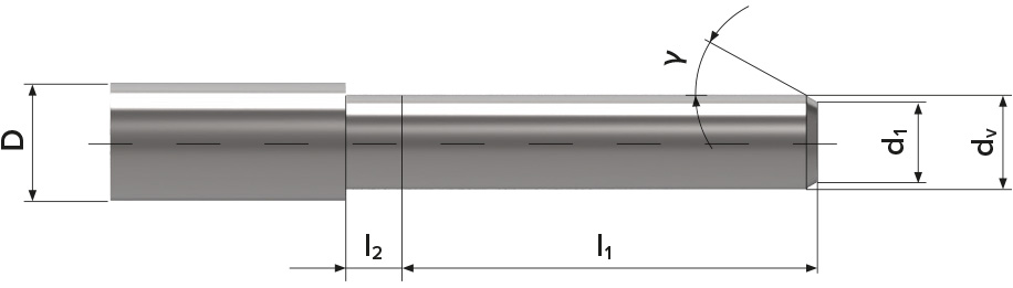
Pre-machined workpiece without undercut
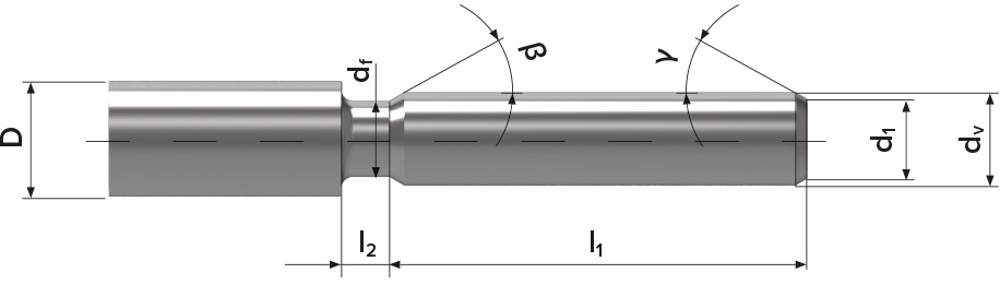
Pre-machined workpiece with undercut
NOTE:
Chamfer the workpiece for V-threads with γ = 15–20° (max. 30°) and for trapezoidal and round threads with γ = 8–15°.
The diameter d1 should be at least 0.2 mm smaller than the minor diameter d3 of the thread.

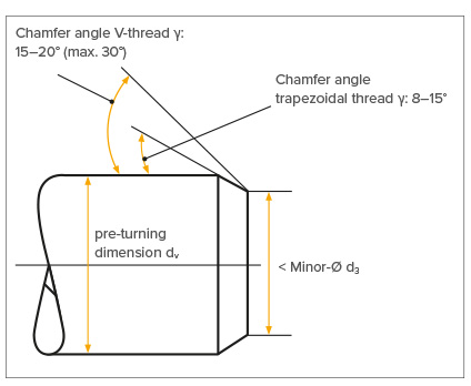
Chamfering the workpiece
D : Shoulder diameter
dv : Pre-turned diameter
d1 : Diameter at the beginning of the chamfer
l1 : Thread length
l2 : Length of thread run-out
γ : Chamfer angle
D : Shoulder diameter
dv : Pre-turned diameter
d1 : Diameter at the beginning of the chamfer
l1 : Thread length
l2 : Width of the thread undercut
γ : Chamfer angle
β : Run-out chamfer
df : Diameter in undercut
THE THREAD RUN-OUT
The smallest possible thread run-out or thread undercut l2 depends on:
- the thread pitch
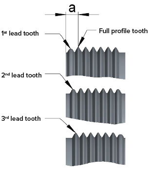
- the lead of the thread roll
The roll lead indicates the forming stages of the roll set, e.g.
3 deformation stages, i.e. the first tooth of roll 3 forms to full thread depth.
a ≈ 1.5 × P
a ≈ 2 × P
a ≈ 3 × P
DETERMINATION OF THE THREAD RUN-OUT

l2 = smallest possible thread run-out or undercut width
a = distance to the first full profile tooth
s = safety distance of the roll to the workpiece collar
EXAMPLE A4-ROLL LEAD
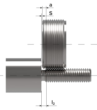
Example Thread M12 x 1,5:
a = 2.8 mm
s = selected 0.5 mm
l2 = 2.8 + 0.5 = 3.3 mm
SETTING THE THREAD LENGTH (FORMING LENGTH) ON THE MACHINE
Conventional machine
- Make sure that the rolling tool is open, if necessary open it manually.
- Move the rolling tool to the desired end position. This position can be determined by the internal stop of the rolling tool or by a stop on the machine and is selected so that the desired thread or forming length is achieved.
- Move back to the start position of the rolling process.
- Close the rolling tool manually by turning the closing lever until the coupler engages.
CNC machine
- Measure the rolling tool in open condition.
- Calculate the traverse path.
- Program the traverse path with the machine control.
- Program the feed stop with a short dwell time when the end postion has been reached so that the rolling tool opens automatically.
PROCEDURE
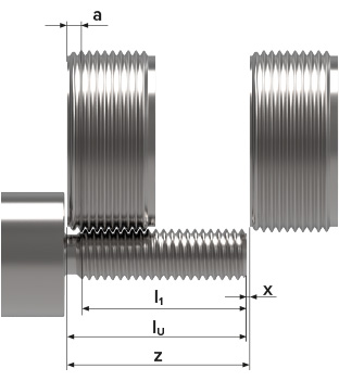
Calculate the traverse path:

z : Traverse path
l1 : Usable thread length
lu : Forming length incl. thread run-out
a : Thread run-out
x : Safety distance to the workpiece (when determining x, it must be taken into account that the rolling tool is shorter in closed condition). (opening stroke s = depends on the tool)
Calculate the dwell time:
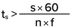
ts : Dwell time:
s : Opening stroke of the rolling tool
n : Spindle speed [1/min]
f : Feed [mm]
THREAD ROLLING
Conventional machine
Workpiece and thread rolling tool are positioned on one axis, the rolling tool is closed and the workpiece rotates. The rolling tool is then manually pressed onto the pre-turned workpiece, either over a curve or with the lead screw, with as accurate a pitch as possible. As soon as the rolls are engaged on the workpiece, the rolling tool is automatically pulled onto the workpiece and forms the thread. No more pressure is required; if pressure was applied with the lead screw, it is switched off. The rolling tool moves to the end position, then automatically pulls out, uncouples and opens. The rolling tool can be moved back to the starting position without contact and is closed again manually.
CNC machine
Normally the rolling tool is clamped into a fixture of the tool turret. The turret moves the rolling tool to the starting position in front of the workpiece. The rolling system moves onto the workpiece in closed condition and thus forms the thread or the profile (in axial direction). The machine feed is to be programmed approx. 3 % smaller than the actual pitch. The rolling system then retracts, uncouples and opens due to the defined dwell time. In the Z-axis it can now be moved back to the starting position.
CHECKING THE WORKPIECE AND FINE ADJUSTMENT
- Inspect the rolled workpiece for dimensional accuracy and the accuracy to gauge.
- Visually check the thread filling degree (shaping of the thread crests).
- Measure the major diameter with a micrometer or caliper gauge.
- Measure the pitch diameter with a flank micrometer or check with the thread ring gauges (go/no go).

1. Thread profile not properly formed
The thread is not true to size. In some cases this degree of deformation may be sufficient for a load bearing thread.
2. Thread profile correctly formed
The radius at the crest of the thread is clearly visible. A closing fold remains in the middle and thus a thread profile is well formed. The diameter of the workpiece must be precisely preturned to prevent the thread crests from being overfilled.
3. Thread crest over rolled
The radius at the crest of the thread is fully closed. A closing fold is no longer visible because the rolling system was set incorrectly or the pre-turned diameter was not produced according to specification. The extent to which the thread profile is formed affects the tool life of the rolls. Over rolled thread crests can lead to roll breakage.
THREAD ROLLING – POWER REQUIREMENT
The power depends on the rolling speed, the material, the profile shape and the thread filling degree. The power requirement can be calculated approximately using the following formula:
N~ C × p × Rm × V × 0.000056 (kW)
C = actor 1 for V-thread, factor 2 for trapezoidal thread
P = thread pitch [mm]
Rm = tensile strength [N/mm2]
V = rolling speed [m/min]
THREAD ROLLING – TYPES
Wagner axial rolling systems are divided into:
Type HELIX
Type RS / RR with roll holder