A thread is a helical ridged groove wrapped around a cylinder or cone. There are both external (screws) and internal threads (nuts), which always form matching pairs.
THREAD TYPES – FUNCTIONS OF A THREAD
- formation of a mechanical connection (fastening thread)
- motion transmission by converting a rotary motion into a linear motion or vice versa (transmission thread)
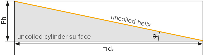
HELICAL CURVE (THREAD LINE)
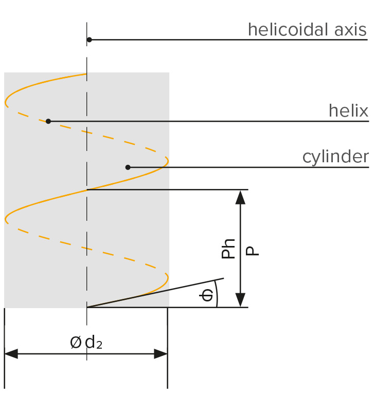
d2 = pitch diameter of the external thread
Ph = slope (with multi-start thread)
P = pitch (with single-start thread)
φ = pitch angle
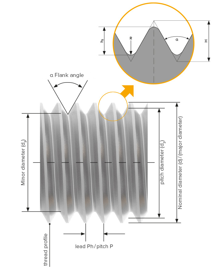
TERMS RELATED TO THREADS (ACCORDING TO DIN 2244)
d = major diameter of the external thread
d2 = pitch diameter of the external thread
d3 = minor diameter of the external thread
h3 = basic major diameter of the external thread
H = height of sharp V thread
P = pitch/lead (single-start thread)
Ph = lead (multi-start thread)
R = radius at the thread crest or in the thread base (root)
a = thread profile angle (called "flank angle" in earlier standards)
RH = international abbreviation for right-hand thread
LH = international abbreviation for left-hand thread
CHIPPING AND CHIPLESS EXTERNAL THREAD PRODUCTION
In the manufacture of threads, a distinction is made between chippless thread rolling and the machining shaping process of thread cutting.
CHIPPING
- thread cutting
- thread turning
- thread milling
- thread whirling
- thread grinding
CHIPLESS
- thread rolling
- thread forming
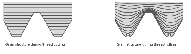
Cut threads acquire their shape by cutting the material, whereby the original grain structure of the workpiece is not changed, but grain structure is interrupted by the cutting process. In thread rolling, the workpiece is permanently plastically deformed by cold forming. In this process, the grain structure of the work hardened material is not interrupted. The prerequisite for thread rolling is a material that is suitable for cold forming, i.e. with a minimum elongation at break percent of 5 %.
THREAD CUTTING (CHIPPING)
Materials
• it is possible to cut materials that cannot be cold-formed, such as grey cast iron, malleable cast iron and gunmetal
Strength
• reduced strength because the fibre course of the material is interrupted
• notch effect in the thread base
Surface quality of the thread flank
• highly dependent on the material and cutting conditions
• higher tendency to corrosion
Production time
• cutting speed: 3 to 40 m/min
• thread profile depth must be produced in several steps
Preparation of the die blank
• precise pre-machining is not necessary
Reworking
• a machined thread can be recut at any time
Tool costs
• low, because the chasers can be reground
Workpiece geometry
• thin-walled unstable workpieces (tubes) can also be cut
THREAD ROLLING (CHIPLESS)
Materials
• all cold formable materials can be rolled
• there are no problems associated with long-chipping materials
• the elongation percent of the material must be taken into account
Strength
• higher due to work hardening of the material
• the grain structure of the material is not destroyed, resulting in a significantly higher static and dynamic strength
Surface quality of the thread flank
• very high, press polished
• very low corrosion tendency
Production time
• rolling speed: 30 to 100 m/min
• thread is produced in only one operation
• very short processing times
Preparation of the die blank
• initial diameter must be pre-machined within close tolerances
• pre-machining diameter corresponds to the pitch diameter
• a chamfer with a chamfer angle of 10 to 30° is required
Reworking
• reworking is problematic due to the material hardness of rolled threads
Tool costs
• high profitability for large series production due to very long tool life
Workpiece geometry
• when rolling threads of thin-walled pipes, a supporting mandral may be required
• the ratio of inner diameter to thread minor diameter should be less than 0.67
THREAD ROLLING – GENERAL CONDITIONS
THE PROCEDURE
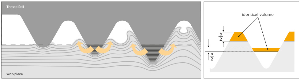
In thread rolling the thread form is produced by cold forming the material. Very high pressure causes permanent plastic deformation of the material. The thread rolls displace the material from the thread core and allow flow in the direction of the thread crest. The grain structure is not interrupted but only displaced. The result is a thread with high strength, profile and dimensional accuracy.
The pre-turned diameter required for thread rolling corresponds to the pitch diameter of the thread. The tolerance is selected so that the desired major diameter of the thread is achieved, but the thread crests are not fully formed. A change in the pre-turned diameter can have an effect on the major diameter of up to 3–5 times. Therefore, a pre-turned diameter that is 0.02 mm larger can result in a major diameter that is up to 0.1 mm larger. Fully formed thread crests have a negative effect on the roll tool life and can lead to roll breakage.
PRECONDITIONS
- exact pre-turning dimension
- elongation percent of the material > 5 %.
- material strength up to approx.1700 N/mm2
FORMING OF THE THREAD PROFILE

1. Thread profile not properly formed
The thread is not true to size. In some cases this degree of deformation may be sufficient for a load bearing thread.
2. Thread profile correctly formed
The radius at the tip of the thread is clearly visible. A closing fold remains in the middle and thus a thread profile is well formed. The diameter of the workpiece must be precisely pre-turned to prevent the thread crests from being overfilled.
3. Thread crest over rolled
The radius at the tip of the thread is fully closed. A closing fold is no longer visible because the rolling system was set incorrectly or the pre-turned diameter was not produced according to specification. The extent to which the thread profile is formed affects the tool life of the rolls. Over rolled thread crests can lead to roll breakage.
ROLLABLE MATERIALS
The material must be cold formable. For V-threads, the elongation percentage should be at least 5 %. The upper limit of the tensile strength is approximately 1700 N/mm2. Please note that the specifications are non-binding approximate values.
Typical materials
- free-cutting and structural steels
- high-alloyed, corrosion and acid-resistant steels
- aluminium and copper wrought alloys with at least 60% copper content
- in order to roll threads on pipes, the wall thickness must be sufficient. This depends on the material as well as the type and depth of the profile to be rolled
ROLLING SPEED/ PROCESSING TIMES
In order to achieve a flow of the material during the thread rolling process, the rolling speed should not be less than 30 m/min. Economical speeds are in the range of 50 to 80 m/min.
ADVANTAGES OF THREAD ROLLING
- extremely short cycle and processing times
- high profile and dimensional accuracy
- reduced notch sensitivity
- increased corrosion resistance through pre-polished thread flanks
- no chips
- efficient and economical production
- higher strength of the thread through cold forming
- long tool life and thus low machine downtimes
PRE-MACHINING OF THE WORKPIECE
Precise preparation of the workpiece is required:
Pitch < 1 mm: tolerance 0.02 mm
Pitch > 1 mm: tolerance 0.03 mm
Pitch > 3 mm: tolerance 0.04 mm
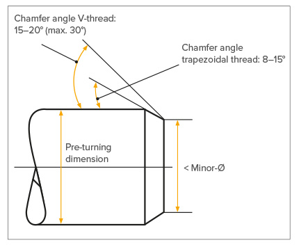
The Chamfering:
For axial thread rolling, the workpiece must be provided with a chamfer at the beginning of the thread to allow the thread rolls to start. The chamfer angle for V-threads should be 15–20°, for trapezoidal threads 8–10°. The diameter at the beginning of the chamfer must be slightly below the thread core diameter. For axial rolling tools, different start /lead variants may be required (for more details, see chapter Axial rolling systems)
THREAD ROLLING CLOSE TO COLLARS
When using the thread rolls in the roll holders, it is possible to perform rolling tasks very close to wide collar diameters. It is possible to substantially increase the collar diameter by grinding out the roll holders (max. to the centre of the roll bolt).
THREAD RUN OUT
When using normal thread rolls, the thread run-out is approx. 2 × pitch for axial thread rolling and approx. 1 × pitch for tangential thread rolling. A thread undercut can be an advantage, but is not required. More detailed information and other run-out possibilities are available on request.
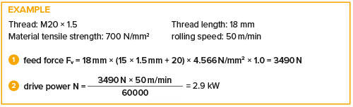
THREAD ROLLING – POWER REQUIREMENT
The power output depends on the rolling speed, the material, the profile shape and the thread filling degree. The power requirement can be calculated approximately using the following formula (Specifications without guarantee):
TANGENTIAL ROLLING
P = Thread pitch [mm]
d = Thread diameter [mm]

AXIAL ROLLING
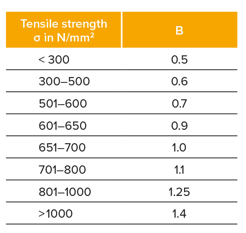
C = factor 1 for V-thread
= factor 2 for trapezoidal thread
P = thread pitch [mm]
Rm = tensile strength [N/mm²]
v = rolling speed [m/min]
CHIPLESS EXTERNAL THREAD PRODUCTION: THREAD ROLLING SYSTEMS
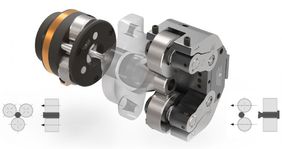
AXIAL THREAD ROLLING IN THROUGH FEED METHOD
The axial rolling system (with three or five rolls) moves in an axial direction on the workpiece and forms the thread. The thread rolls are provided with a pitch-free profile. Pitch and profile corresponds to the thread profile. The thread pitch is produced by the inclination of the thread rolls in the roll holder. The machine feed must be programmed approx. 3 % smaller than the actual thread pitch. The length of the rolled workpiece is not limited by the tool. Automatic opening of the rolling system at the end of the thread is activated by a programmed feed stop. The workpiece is released by the opening mechanism of the rolling system. The rolling system is returned to basic position in rapid traverse. In order to process the next workpiece, the rolling tool is closed manually or by a closing device.
Stationary Type:
The stationary Wagner thread rolling tool is designed for use with rotating workpieces. This design is used, for example, on the turret of a lathe.
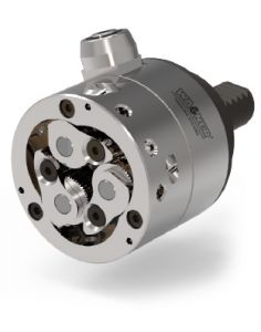
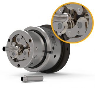
Rotating Type:
The Wagner rotary thread rolling tool is designed for use with stationary workpieces. It is used, for example, on the centre sleeve of a machining unit or on the spindle of a slide unit.
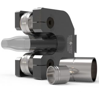
INFEED METHOD WITH TANGENTIAL TOOLS
The tangential rolling system (with two synchronized rolls) moves in tangential direction to the workpiece and forms the thread. Profile and pitch of the thread are defined by the roll geometry. The roll diameter is a multiple of the thread diameter.The tangential tool moves at a constant feed rate against the rotating workpiece. The feed motion is perpendicular to the workpiece axis.
The thread rolls are set in rotation by contact with the workpiece and form the thread as the tool continues to advance. When reaching the center of the workpiece, the rapid return is initiated without dwell time. It is not necessary to open/close the tool.
The length of the threads depends on the size of the rolling system and the width of the thread rolls.
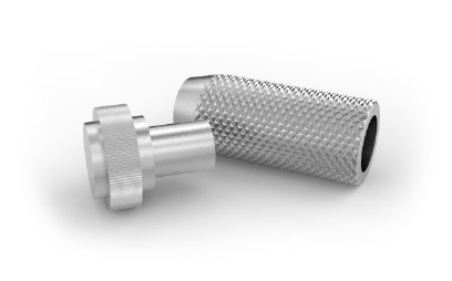
WHAT IS KNURLING?
Knurling is a manufacturing process for producing non-slip surfaces on cylindrical components, in which patterns are embossed into workpieces.
PROCEDURE
Basically, a distinction is made in the production of knurls between non-chipping “knurl pressing” or “knurl forming” and cutting “knurl milling”. When knurling with axial and tangential rolling systems, “knurl pressing” is used. Cold forming is used to roll the profile of the knurling roll onto the workpiece. As with thread rolling, the profile tips of the rolls are pressed into the workpiece and the displaced material flows into the gaps of the rolls, i.e. the diameter of the workpiece becomes larger.
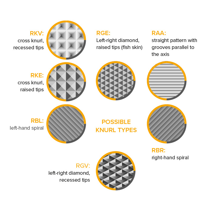
According to DIN 82, all knurl types can be rolled, provided that the material is cold-formable.
Wagner knurling tools are suitable for demanding applications and large quantities due to their outstanding quality. We produce the various knurl forms with the pitches from 0.5 to 2 mm.
ADVANTAGES
- high strength of the work piece, as the grain structure of the material is not affected
- high wear resistance due to hardening of the surface
- high efficiency
WAGNER SYSTEMS FOR KNURLING
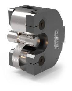
TSW-Tangential system for knurling and beading
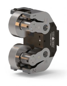
Tangential system for thread rolling, knurling and beading
Axial rolling system for thread rolling and knurling
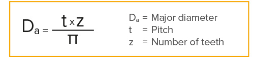
STANDARDIZED PITCH
Knurls are used to give surfaces a better grip (e.g. medical instruments), to improve the appearance (visible knurl), or to create a frictional connection between a hub and a shaft. In contrast to splines and serrations, where the tooth shape and number of teeth are precisely defined, the outer diameter is the decisive criterion for knurling. The outer diameter is calculated according to the formula opposite. The preferred pitches according to DIN 82 are 0.5; 0.6; 0.8; 1.0; 1.2; 1.6 and 2.0 mm.
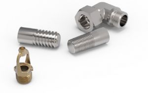
CHIPPLESS PRODUCTION: BEADING AND FORMING
Both the axial systems and the tangential systems can be used to roll beads, radii, parallel grooves and other shapes. The tools are also suitable for tapering tubes and smoothing surfaces.
With the tangential systems it is possible to achieve twist-free surfaces with excellent surface quality by smoothing. Twist-free surfaces are often required for workpieces with a sealing function.
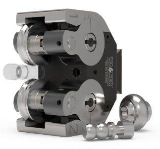
Tangential rolling system B10 for smoothing a spherical surface
Tangential rolling system TSW with special rolls for rolling in a cuffed fit
Rolling system RR22-2 for rolling up a hose coupling
THE PROCEDURE
Thread cutting is a machining process in which material is cut out of the work-piece by means of chasers in order to produce a thread.
The cutting system moves in axial direction on the workpiece and cuts the thread. At least four chasers are provided with a pitch-free profile. Pitch and profile correspond to the thread profile. The thread is produced by the inclination of the chasers in the chaser holders. The feed corresponds to the thread pitch. The length of the thread is not limited by the tool. At the end of the thread, the opening mechanism of the tool is automatically activated. The tool releases the part and the tool returns in rapid succession. To machine the next workpiece, the tool is closed manually or by an automatic closing device.
Stationary Type:
The stationary Wagner thread cutting system is designed for use with rotating workpieces. This design is used, for example, on the turret of a lathe.
Rotary Type:
The Wagner thread cutting system in rotary design is designed for use with stationary workpieces. It is used, for example, on the centre sleeve of a machining unit or on the spindle of a slide unit.
MATERIALS
Thread cutting can be used for a wide range of materials: free-cutting and structural steels, high-alloy steels, copper and aluminium alloys and non-ferrous metals. Threads can also be cut economically on materials that cannot be cold-formed, such as gunmetal, malleable iron and grey cast iron. Plastics are also possible. The material strength should not exceed 1300 N/ mm2.
THREAD TYPES
- V-threads: Regular or fine threads, left or right hand threads, cylindrical or conical threads
- Trapezoidal threads, round threads, other special shapes
- British or American standard threads
ADVANTAGES
- no exact pre-processing of the workpiece necessary to guarantee tolerances
- short cutting times
- threads on thin-walled pipes possible
- high efficiency due to low tool costs
- short set-up times
- cutting of threads in a single operation, saving cycle time compared to thread turning in several passes
- economic efficiency due to the ability to regrind chasers
- modular design of the systems with large operating ranges
- central diameter adjustment, fine adjustment possible in the machine
- suitable for materials that cannot be rolled
- tools can be used stationary and rotationally
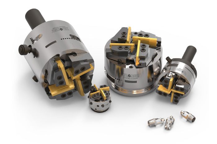
THE CHASERS
The chasers have a parallel thread profile, i.e. threads of different diameters can be cut with the same thread pitch using a chaser set (e.g. M6, M8 × 1, M10 x 1 ...). However, depending on the diameter and the pitch angle, the appropriate chaser holders must be used.
The chasers are adapted to the machining task in size, throat and thread profile, that is, they are different:
1. in the thread profile (e.g. Metric, UN, Whitworth ...)
2. in the throat (short, medium, long)
3. in the chaser quality (HSS, HSSE, nitrided, coated ...)
4. in the dimensions (chaser size S02–S15)

Short throat:
- for workpieces with thread against collar or short thread undercut
- thread run-out approx. 2 × thread pitch
Medium throat:
- for blank or pre-turned workpieces without or with slight oversize
- thread run-out approx. 3 × thread pitch
Long throat:
- for workpieces of rolled material or with oversize
- thread run-out approx. 4 × thread pitch
Custom-made throat:
- throats customized to the machining process are possible
The length and the angle of the throat influence the thread surface and the tool life. The longer and flatter the throat, the longer the tool life and the better the surface finish.
MULTI-CUTTER TURNING SYSTEMS
THE PROCEDURE
With the multi-cutter turning systems, workpieces are reduced in diameter in the classic metalcutting process of turning. The cutting tool moves in axial direction on the workpiece and cuts the workpiece into shape with at least three inserts. The length of the cut workpiece is not limited by the tool. With the Wagner multi-cutter turning systems workpieces can be reduced in diameter up to 6 mm in one pass. The starting material can be round, square or hexagonal, drawn or rolled.
In addition all machinable materials can be machined.
ADVANTAGES
- very efficient cutting performance due to 3 to 4 times higher feed rate ensuring a high level of efficiency
- extensive operating range
- easy handling due to central diameter adjustment
- high turning accuracy (0.01–0.02 mm in diameter) is achievable
- large and unstable extension lengths can be turned with good results
- high surface quality due to original Wagner opening function. When the turning length is reached, the four carbide inserts are lifted off the workpiece when the tool is opened. The contact-free return ensures a flawless workpiece.
- use of DIN ISO inserts or Wagner precision inserts